Steam Controller: I can has Hall Effect module!
Steam controller is a nice controller, but discontinued and they will begin to fail!
My analog joystick module had just became too worn. It started drifting down sometimes and extreme inputs (100%) was no longer possible. I also looked at an analog scope and noticed the signals are very, very noisy!
Cleaning the module (the actual potentiometers) did reduce the noisyness, but extreme inputs were even more difficult to do.
It is difficult to source analog modules. The ones I got had huge deadzones and looked terrible on hardwaretester.com/gamepad .
So, I ordered a bunch of (possibly better quality?) analog modules from konsolowo along with PS4 Hall Effect modules. I just decided I wanted to try how the Steam Controller handles them.
I had already determined the pinout of the Steam controller. It doesn’t use any of the common pinouts, it’s a cross breed between PS4 and Xbox =). You need the black sensors on both sides, in other words, ground is always furthest away from the button (pin 3). It’s the black sensor if you order the modules with black and yellow (orange) sensors =). By combining sensors from 2x PS4 (or Xbox) you should be left with one suitable for the Steam Controller and one suitable for Xbox PS5 (for reference reddit.com/…/ps5_ps4_xbox_hall_effect_analog_stic…).
Now, when changing the sensor I loosened a magnet. You might not need to calibrate if you don’t, but I was forced to. These sensors can and should be calibrated to get the centerpoint right. However, I’ve noticed (when playing with the dirty analog module) that the Steam Controller uses some kind of auto-calibration; it’s “calibrate” option does nothing in Steam and there is no manual calibration option at all. The centerpoint is calibrated automatically!
But if the magnets are not aligned, you might either bottom out on the 0v (minimum, obviously) or 2.8V (maximum). Also, if the “center” value is way out of range, the Steam Controller (Firmware!) might not be able to auto-calibrate the center.
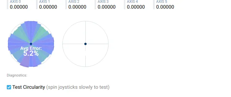
There is something to be improved on the maximum range. See the attached screnshot - this is about as good as it can get. I was once able to get an even better result, but it’s a bit inconsistend.
Also, I suspect that sometimes the calibration might get corrupted during play. I’m not sure what is going on, but I suspect it’s because when pressing the thumbstick button, the values might overshoot because of how the hall sensors work. I’ve seen this problem with an 8bitdo controller (Pro2 Hall Edition), but it has a manual calibration option, too. And, the Steam Controller calibration algorithm is meant for analog potentiometers.
WARNING: Some actual long-term testing to make sure these modules are actually useful, and to determine if the above problem is a real one and how severe!
ABOUT CALIBRATION:
It’s a bit more difficult to calibrate the module on a Steam Controller because of the auto-centering feature on the controller. It’s still worthwhile since the circularity test will be totally out-of-whack if you are bottoming out the sensors. A multimeter and an oscilloscope can become handy to help to see if you are bottoming out. A good rule of thumb is to measure the neutral (center) raw value from the controller, it should be around 1.4 - 1.5V. If you can not measure during calibration, then if the circularity test is “lopsided” vertically or horizontally, then the input needs to be moved away from that direction. When calibrating, and the firmware somehow determining the maximum range, a lot of rebooting is needed (since the situation is changing all the time)!
If you try this replacement/mod/upgrade, be wary OF THE FLEXCABLES TO THE TOUCHPADS. The Steam Controller will not boot if they are not connected. The flexcables are delicate. I had best ergonomic results by unscrewing the modules and carefully having the controller on a table with the modules resting on the PCB. Don’t try to do calibration in some un-ergonomic way trough some narrow space, you’ll just get bad results, get frustrated and possibly damage the flex cables.
TL;DR:
Is it worth to put in Hall Effect modules? Maybe. If your analog pots are really end-of-life, then they sure are usable replacement. But if you can find good quality analog joystick modules, with matching potentiometers with no deadzone, you are probably better off with them. Calibration might be even more tiresome than on some other controllers, but results might actually be better because of the intelligence in Steam Controller. I hope the controller was properly software-calibrateable (no auto-calibration). A possibly remedy: opensteamcontroller and open firmware?
I might make a comparison to proper analog modules, but it’s a bit tiresome changing the sensor modules. I’ve never tested the Steam Controller with intact, original analog pots on hardwaretester.com, and I could not find any previous screenshots/test. It’s possible the firmware never calibrated the analog pots any better; I don’t know what the reference functionality was.
Pictures might be coming online later. If you have any questions, please do ask!